|
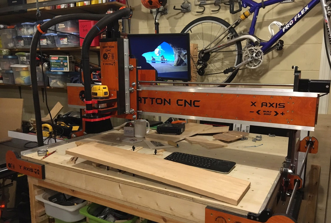
This final has the axis labels i used for my Gatton CNC in both DXF & SVG format. Enjoy
0 Comments
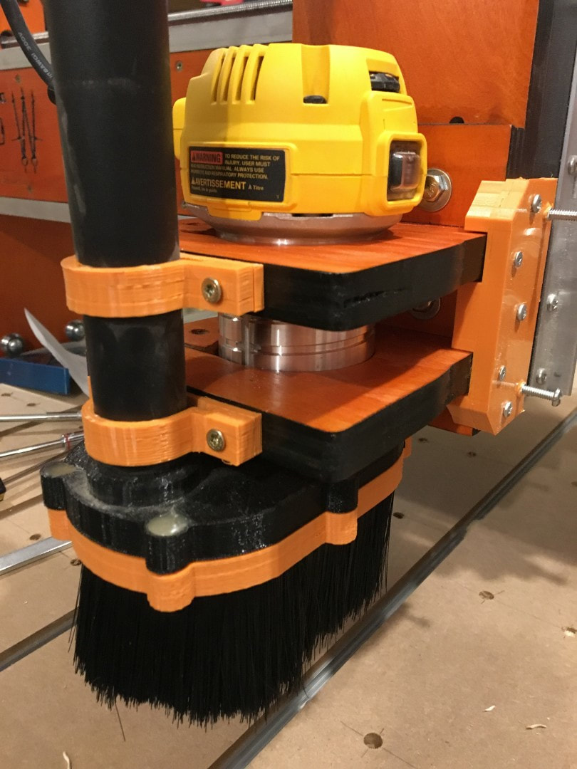
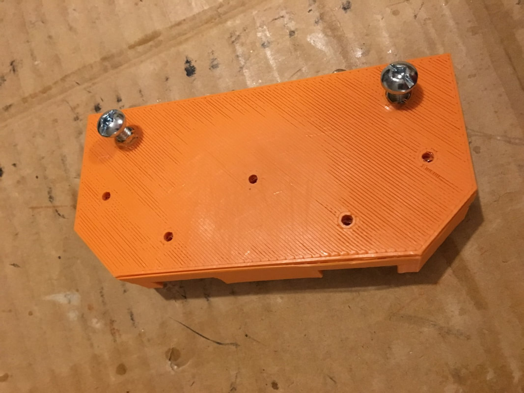
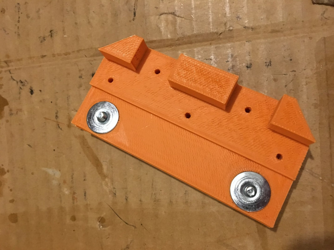
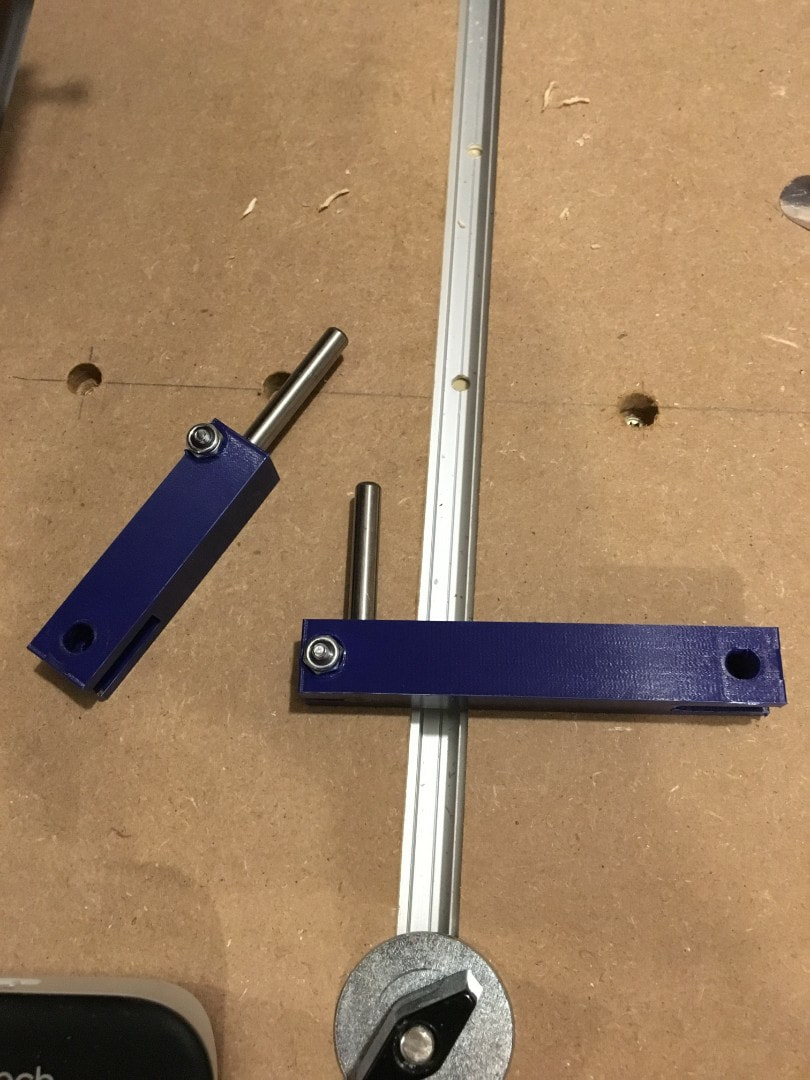
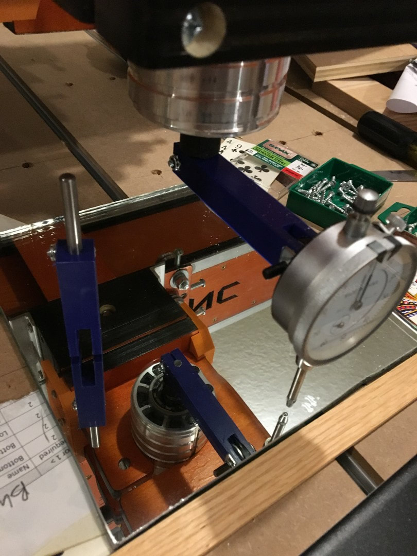
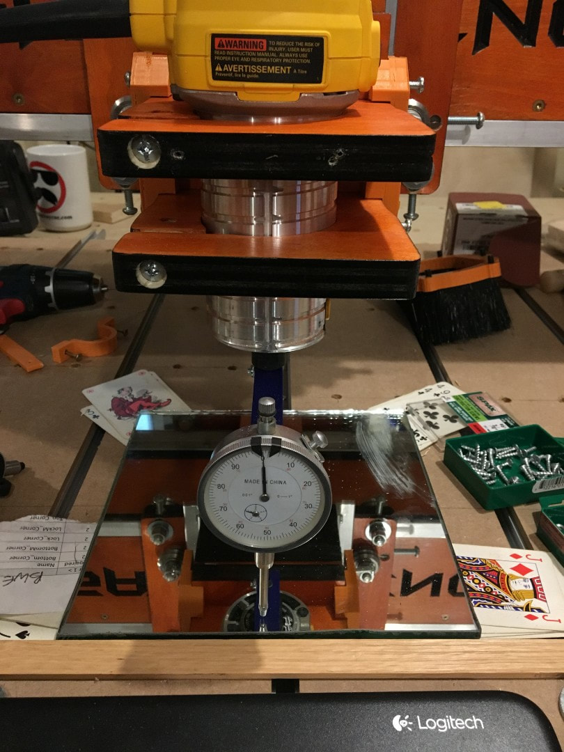
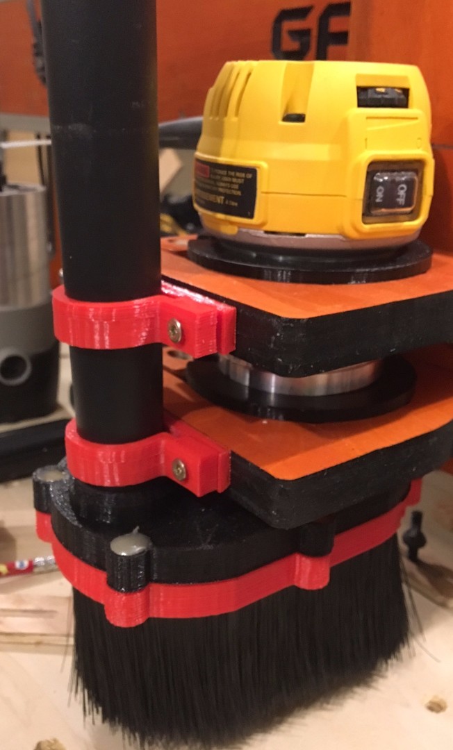
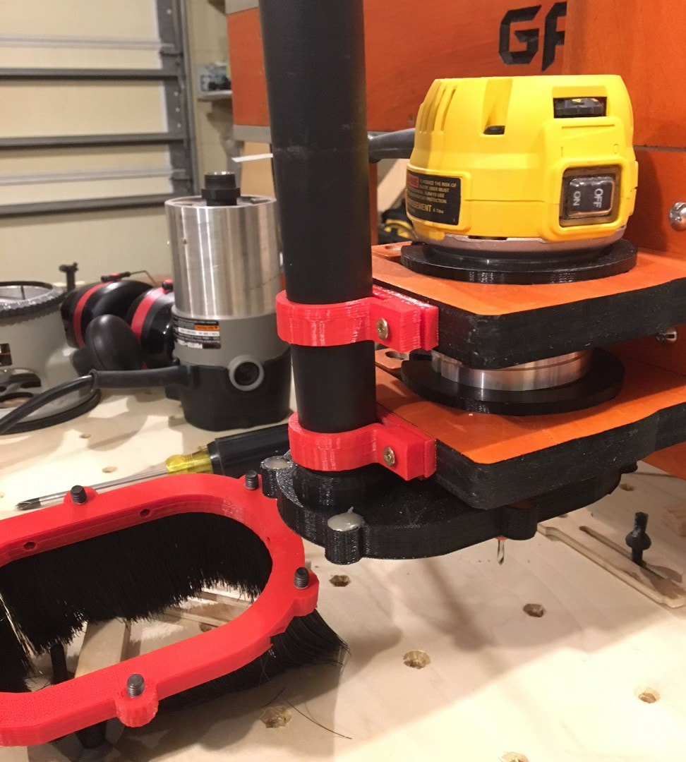
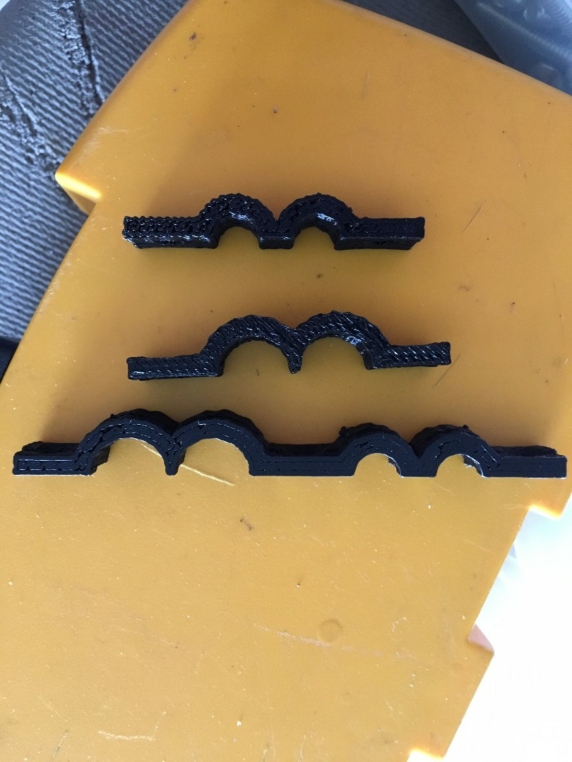
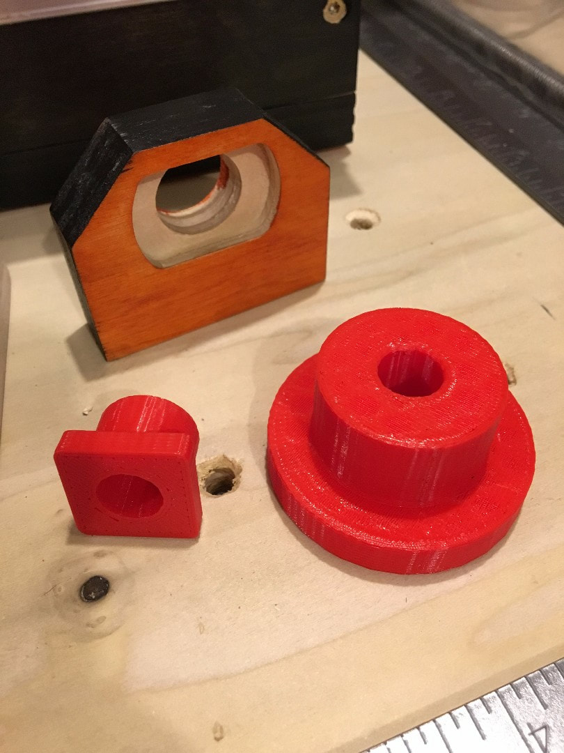
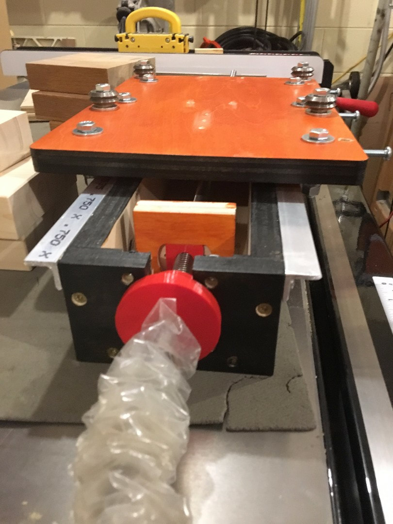
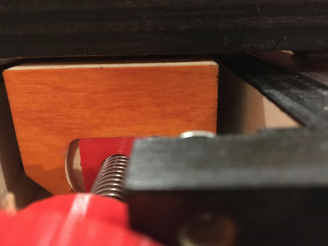
To make the side to side tilt adjustment i designed and 3D printed some adjustment blocks. The link to the file can be found here. https://www.thingiverse.com/thing:3052668 The next step after watching Mark Lindsay video was to tram the router, so i 3D printed some tramming bars to make it quick and easy. The files can be found on Thingiverse. https://www.thingiverse.com/thing:3052670 So i finally got around to making an updated mount for the Dewalt DW611 router. The DXF files are also attached. 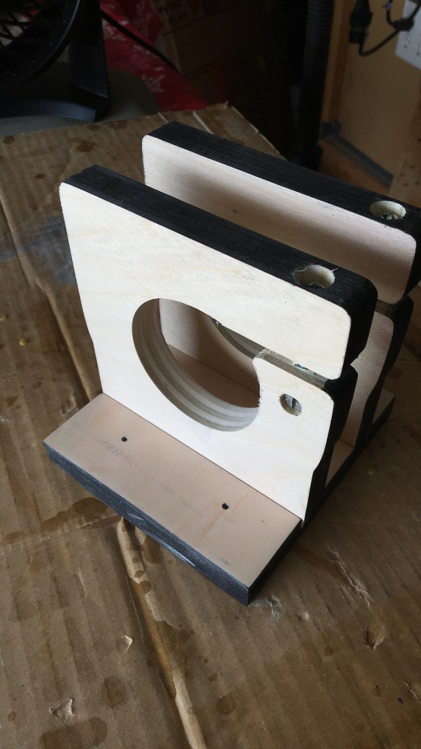
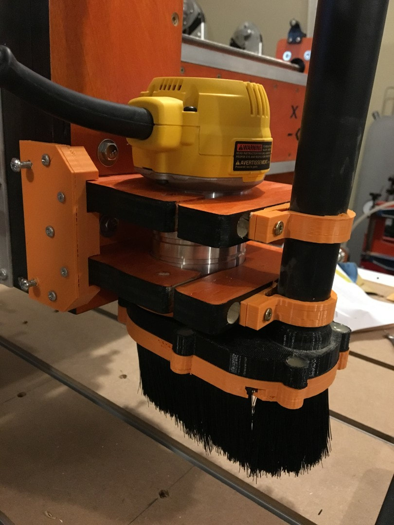
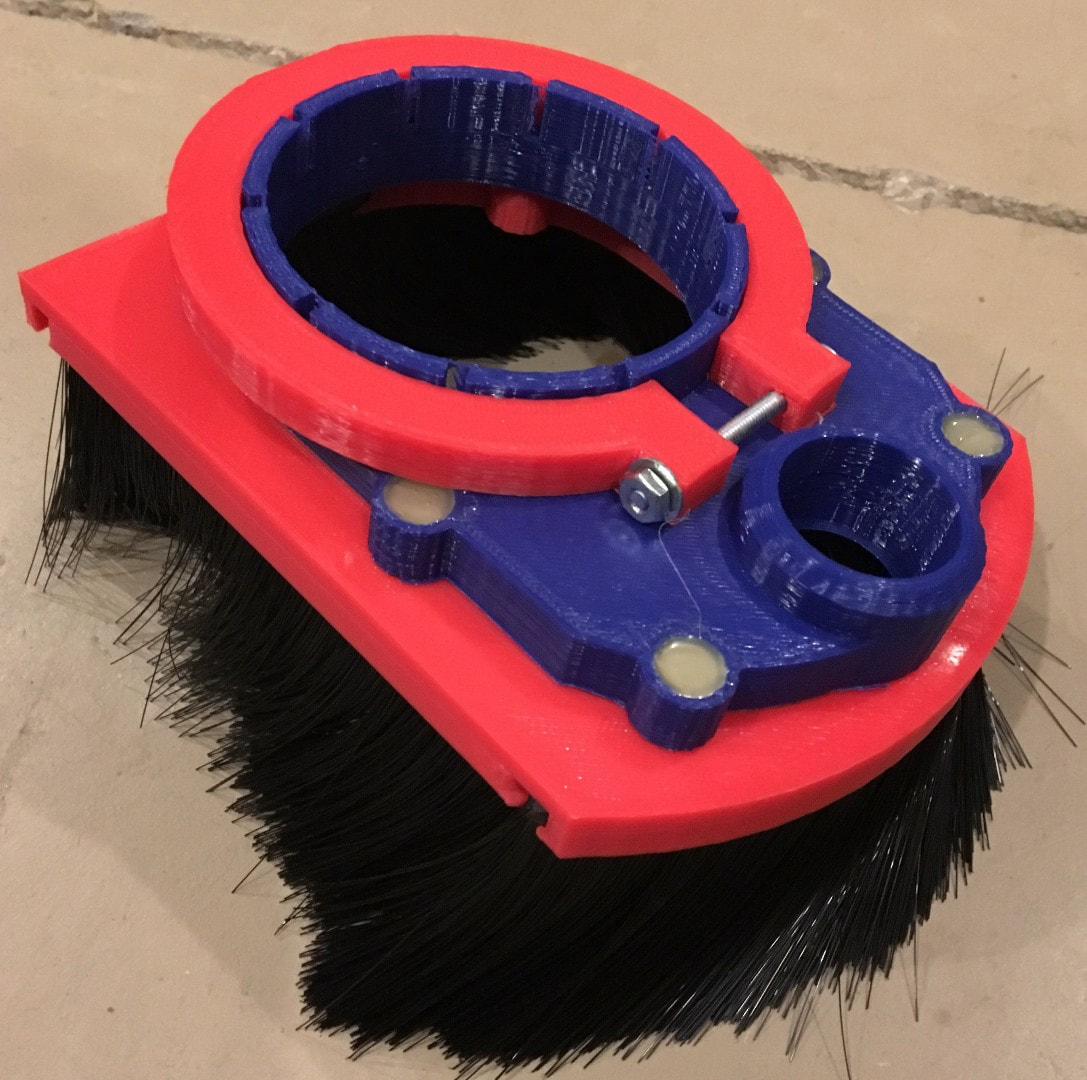
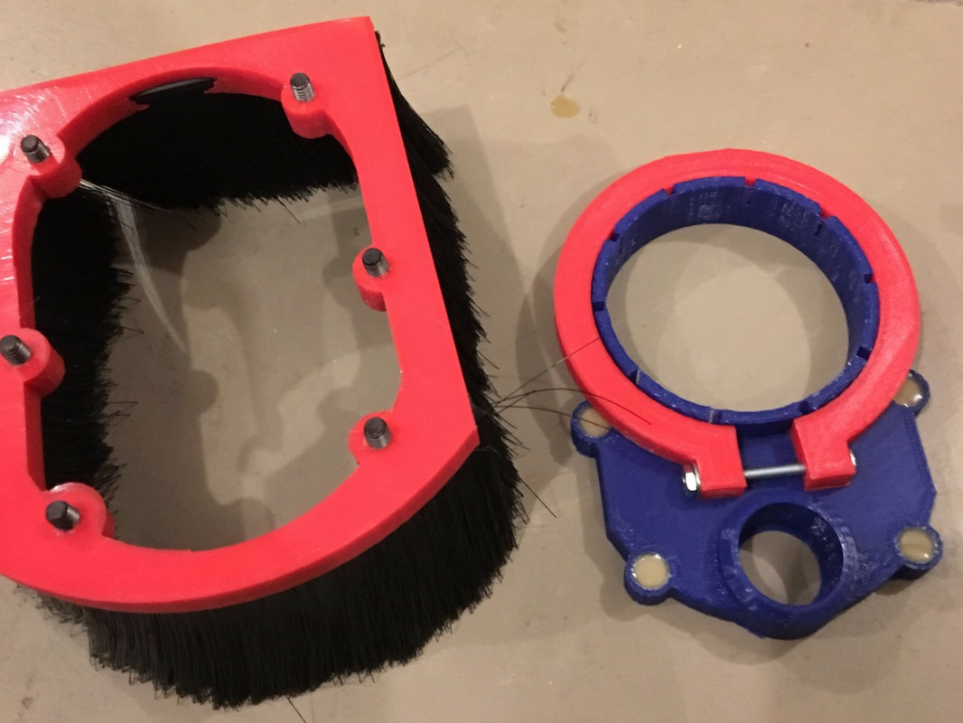
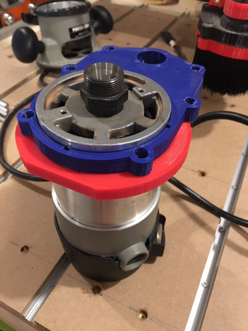
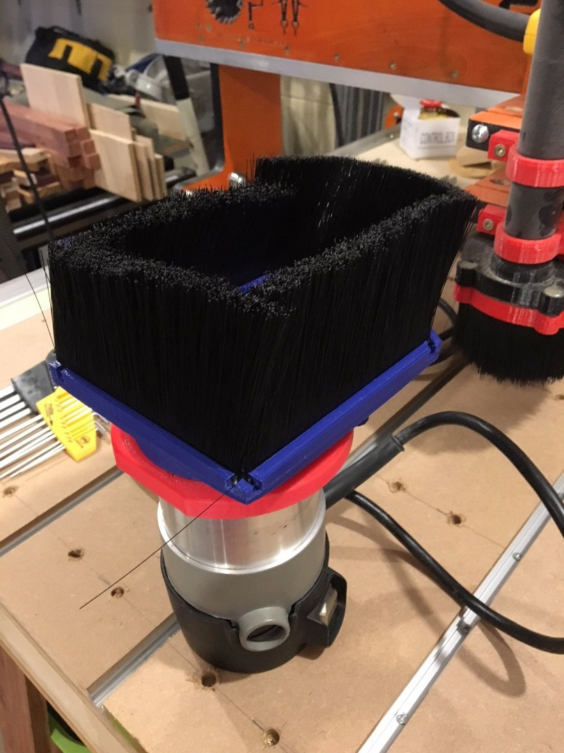
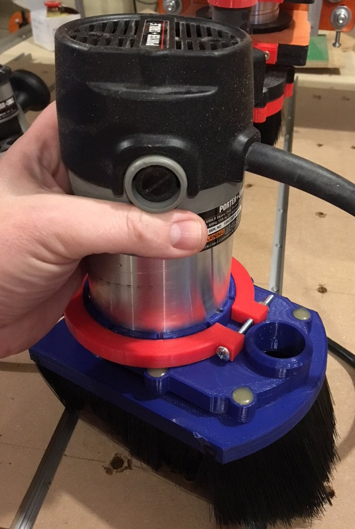
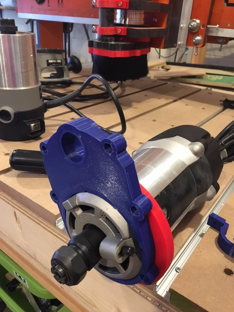
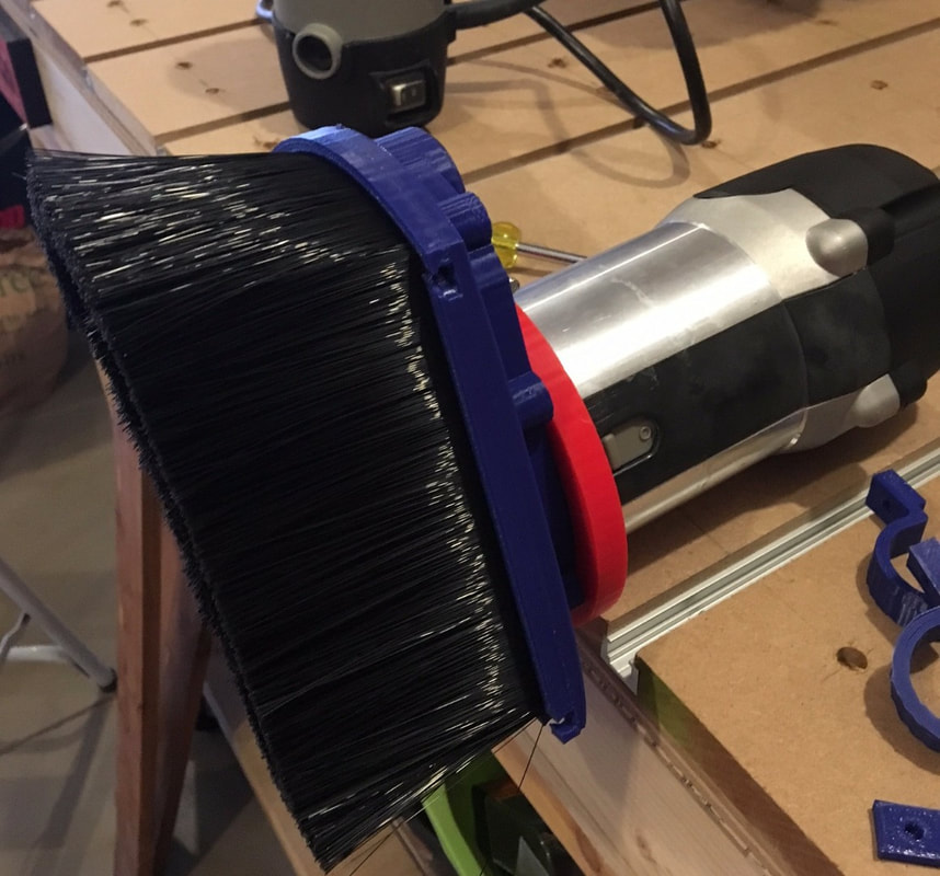
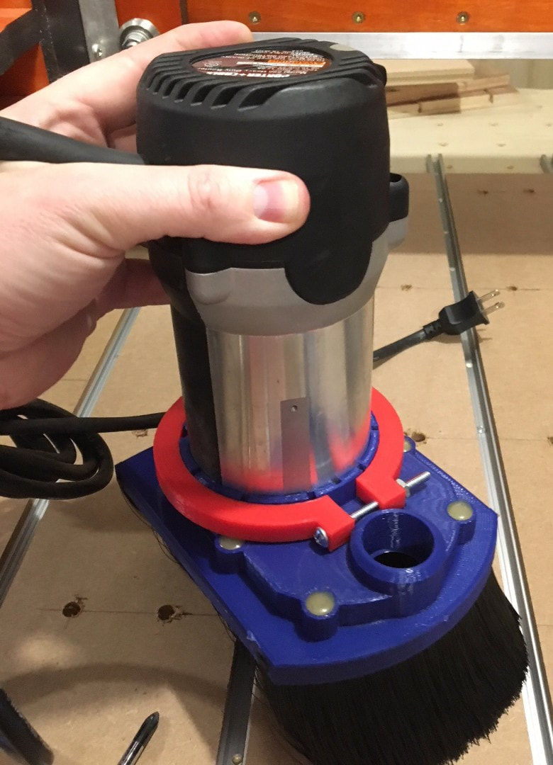
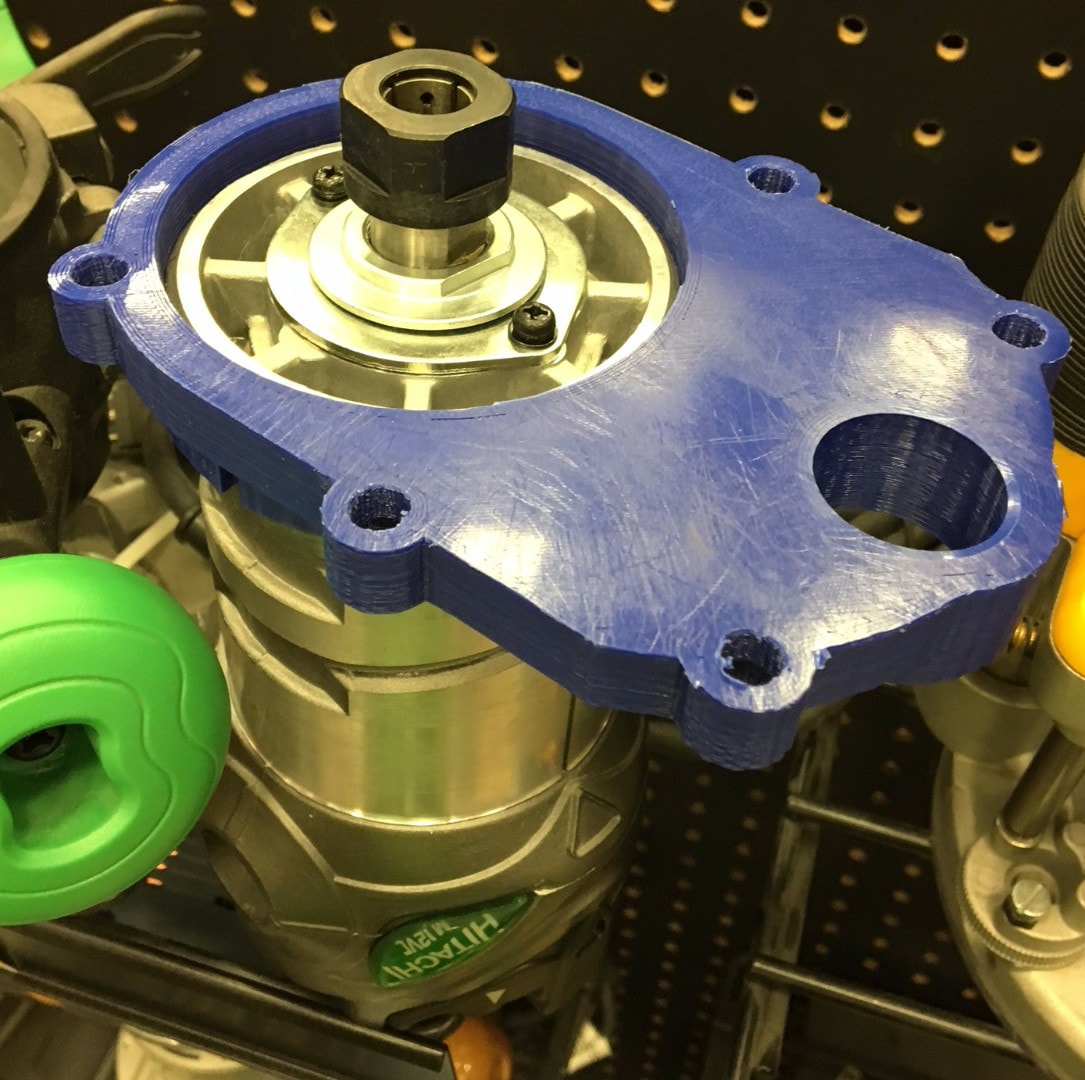
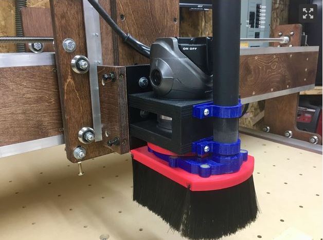
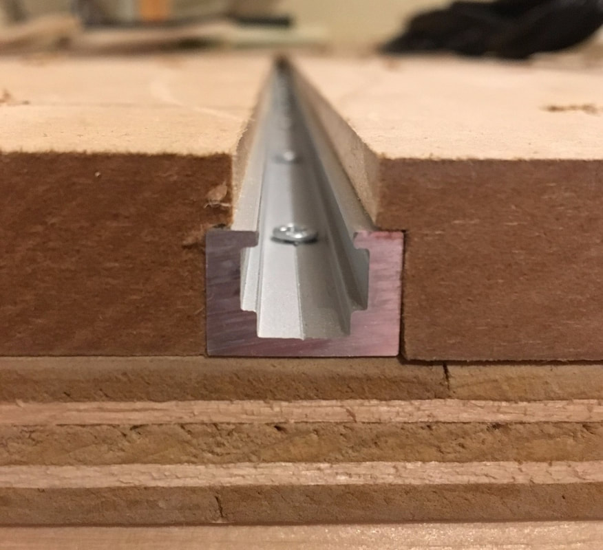
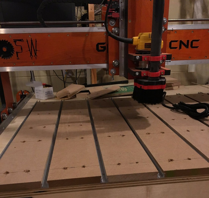
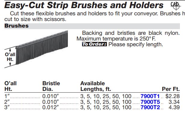
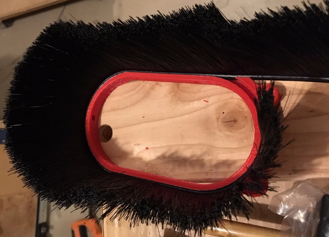
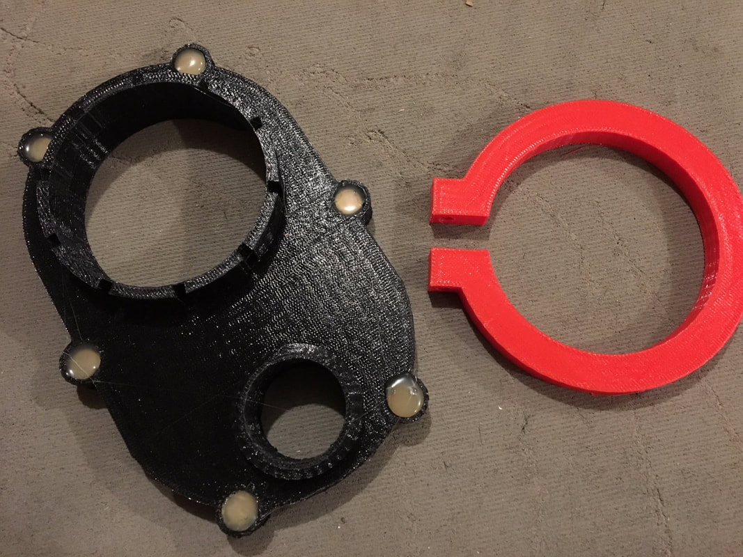
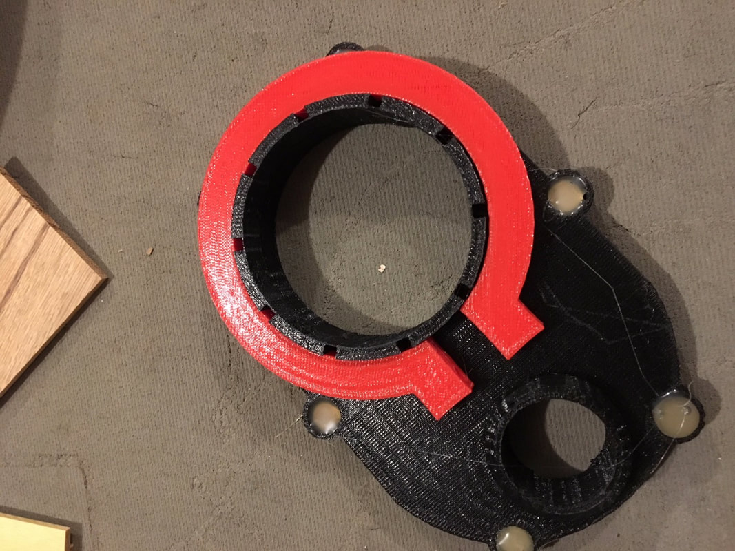
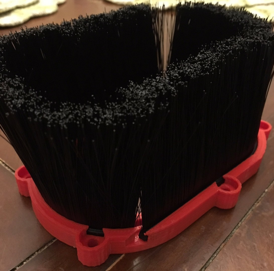
Dust shoe designed and 3D printed for the 3.5" Porter Cable 690 & 890 Router. Link https://www.thingiverse.com/thing:2900890/#files Dust shoe designed and 3D printed for the 3.25" Hitachi M12VC Router. https://www.thingiverse.com/thing:2900887 Installed the new T Tracks and MDF spoilboards. https://www.orangealuminum.com/t-tracks-and-framing-systems.html I finally got the dust shoe designed and 3D printed. It is installed and working great. I use a shopvac for dust collection so here is a link to the hose i use. https://www.amazon.com/Shop-Vac-9051200-1-25-Inch-8-Foot-Hose/dp/B002YLRE1G/ref=sr_1_1?ie=UTF8&qid=1509036999&sr=8-1&keywords=shop+vac+hose I used the McMaster brush part # 7900T2. https://www.mcmaster.com/#7900T2 They do have 1" and 2" also. These are the magnets for the upper part. https://www.amazon.com/gp/product/B01MFHNHNW/ref=oh_aui_detailpage_o09_s00?ie=UTF8&psc=1 In the lower part it just uses 1/4-20 SHCS 5/8" long. I used a few bungee cords to hang the hose. Here is the link for the 3D printer files. https://www.thingiverse.com/thing:2900889 The cncjs software which is explained in the instructions i posted.
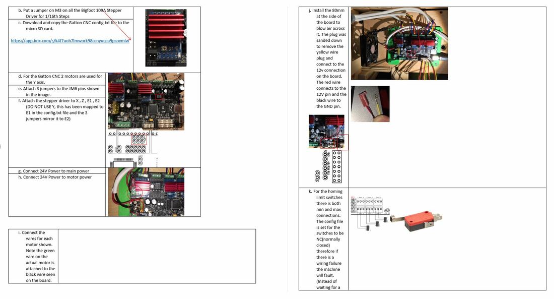
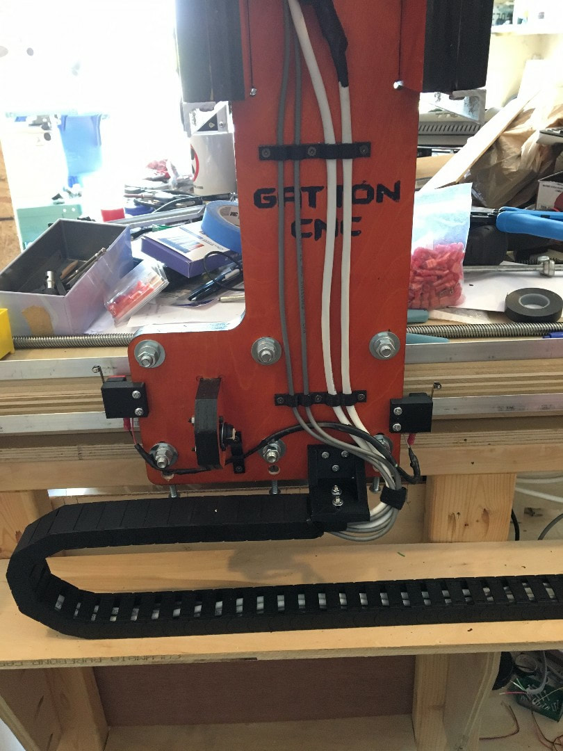
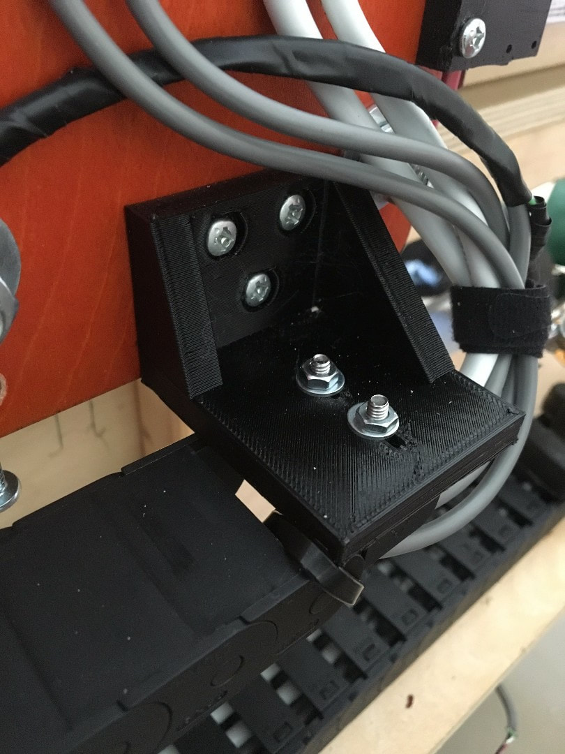
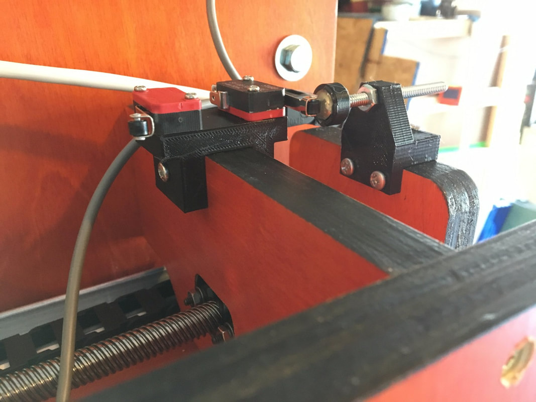
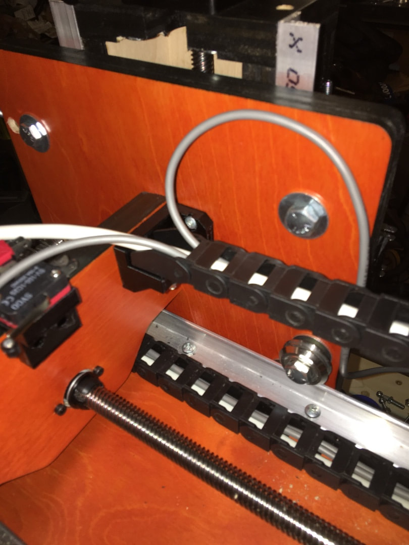
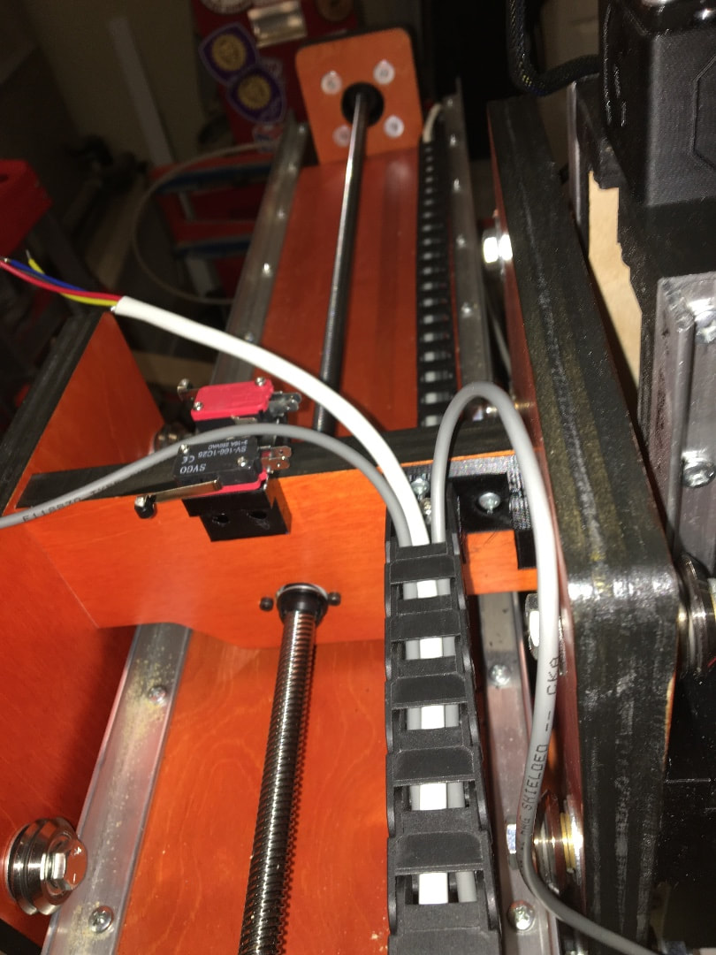
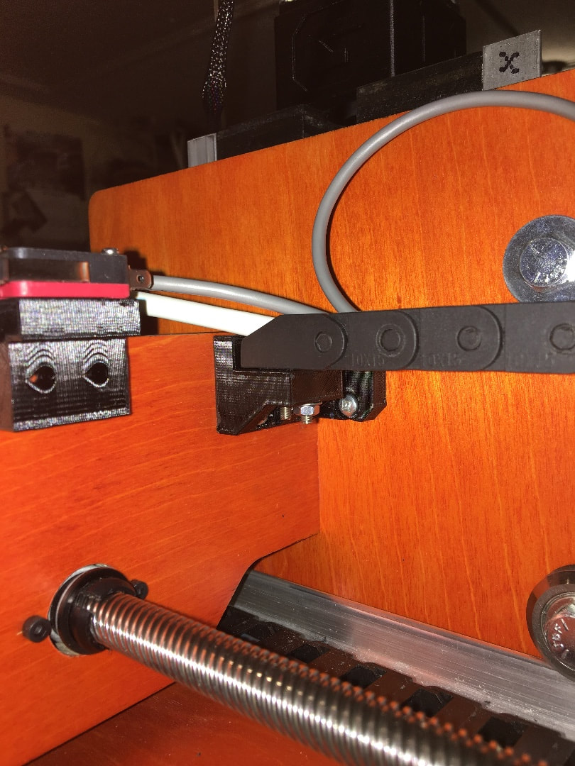
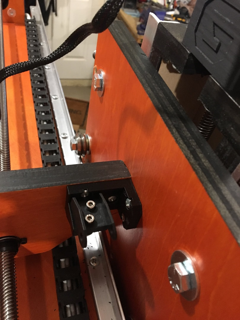
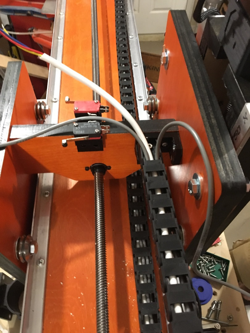
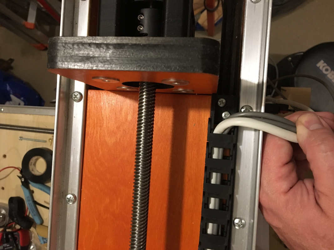
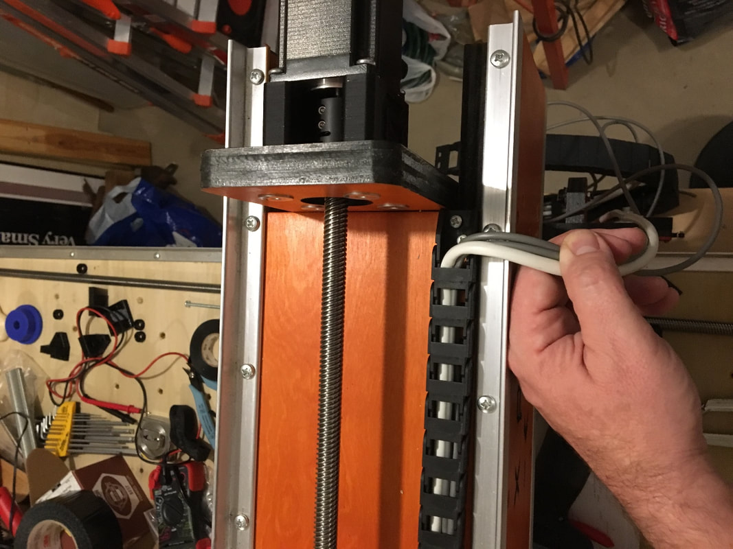
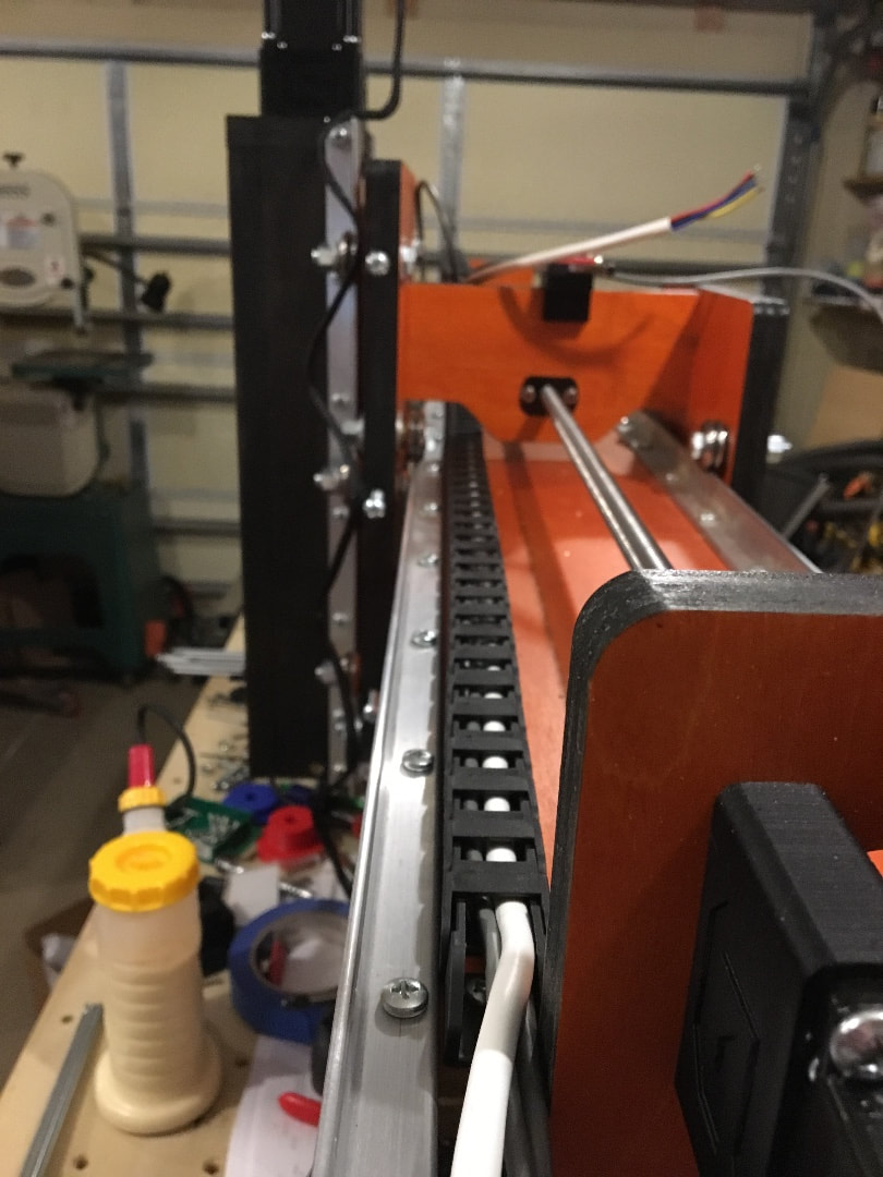
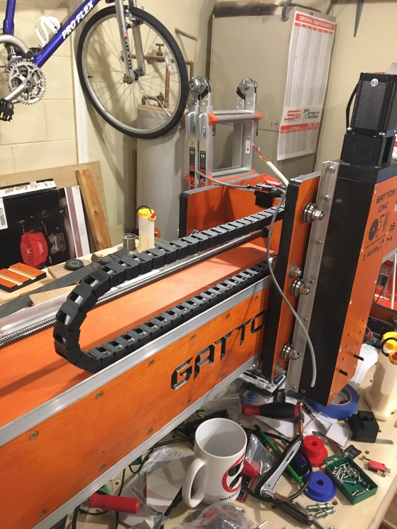
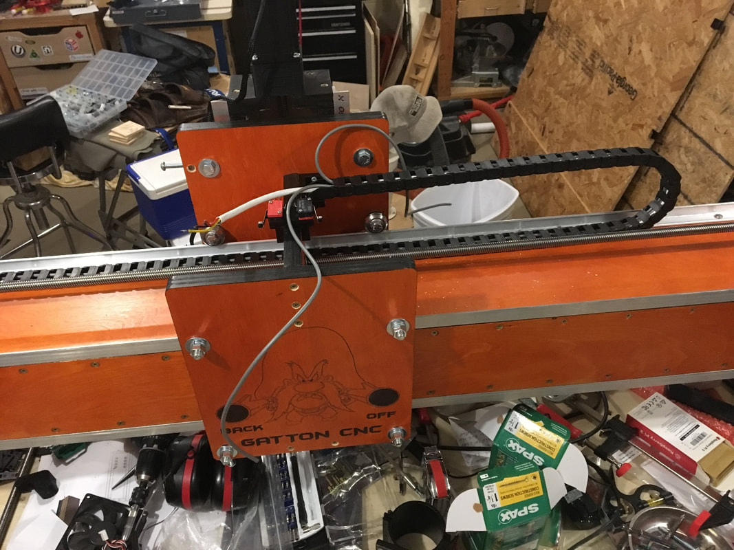
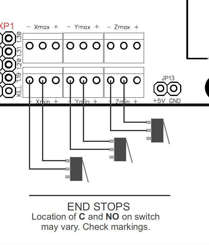
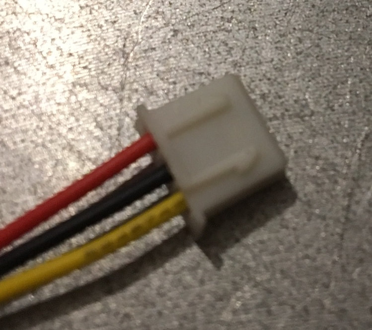
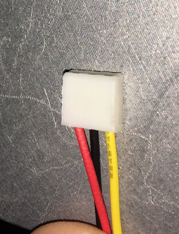
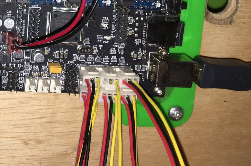
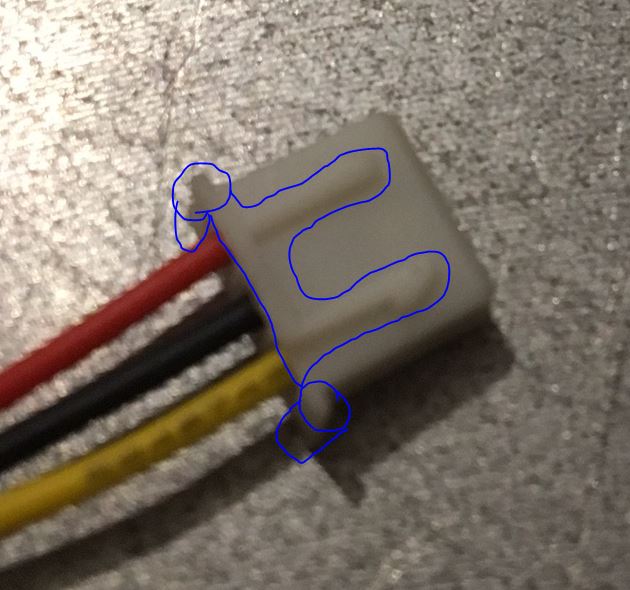
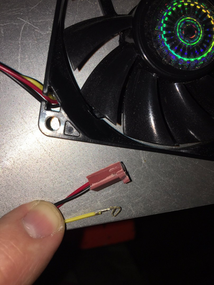
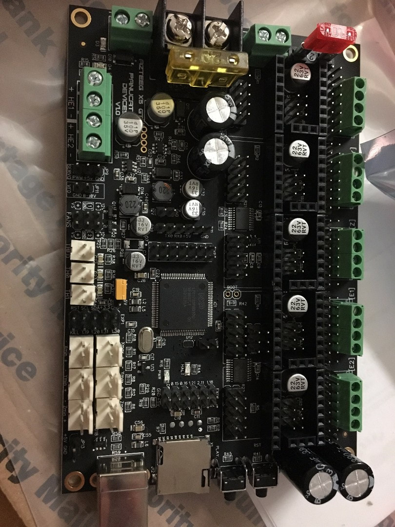
https://app.box.com/s/gctl5nbegya9xq79d8o13vamd1pzfxr2 the direct link for cncjs is https://www.npmjs.com/package/cncjs It works great i am very impressed with it. So just in case anyone else wants to use the Azteeg X5 GT Smoothieboard i wrote down all the steps to get everything working. The approximate cost for this option is around $430. This board already has the IO to control the router and vacuum relays, min and max limit switches and the z probe. Any software that can control a Smoothieware board will work so there is no need for Mach 3 or a old parallel port pc, as it uses USB. This is the link to the document. https://app.box.com/s/gctl5nbegya9xq79d8o13vamd1pzfxr2 This is the link to the config file for the Gatton CNC. https://app.box.com/s/k4f7uoh7lmwork98ccnyucea9psnvmlw This is the link to the V Carve (mm) Post Processor https://app.box.com/s/vbwk3nyhem0jt7vp047bl3bsctesz0pb This is the link to the V Carve (inch) Post Processor https://app.box.com/s/7jh91jshfq707b4898dk81fdj45sykwd So the machine is alive and running. I ran the first 'Hello World' program tonight. Here is a link to the DXF file. https://app.box.com/s/hxc31qpw7kucww6u2i4erde1uyqtg8jm Here is the video of the first cuts!!!! Woo Hoo Y axis drag chain installed and running smooth. And yet more 3D printed clips to hold the wires in position neatly. Drag Chain Bracket https://www.thingiverse.com/thing:2515870 Cable Clips https://www.thingiverse.com/thing:2550477 Tonight i managed to attached and wire the X axis limit switches. Again using 3D printed brackets, and the files are located here. https://www.thingiverse.com/thing:2515781 The 3rd photo shows the X axis drag chain sneaking by the left upright. I think i am going to print an angled guide to make sure the drag chain doesn't get pushed up against it. So i 3D printed yet another bracket for mounting the X axis drag chain. The files to print one are located here. https://www.thingiverse.com/thing:2515867 Its a 10x15 drag chain and fits under the X axis lead screw nut block. So i started running the wires for the limit / homing switches which are wired as separate min and max switches directly to the Azteeg X5 GT board. I ordered these plugs to make it easy. https://www.amazon.com/gp/product/B00TGSD6PI/ref=oh_aui_detailpage_o08_s00?ie=UTF8&psc=1 The plugs did have some raised clip / location pieces on the plug which i removed with a disc sander. Very easy. I did have one wire where 2 of the wires fell out the plug but luckily i had a pack of 10. Even though there are 3 wires on the plug and board as can be seen from the wiring diagram only the red and black wires (Shown on the board in the photo below) are connected to the limit switches. So the Bigfoot stepper drivers need fan cooling. The Azteeg X5GT has a 12V output and i already an 80mm fan so i 3D printed some small feet to attach to the fan and mount next to the board. The fan has 3 wires but the yellow feedback wire is not required to using the disc sander i sanded that side off the plug so it would clear everything on the board. The 3D printer files are here, https://www.thingiverse.com/thing:2515771 So for the motor wiring i used this,
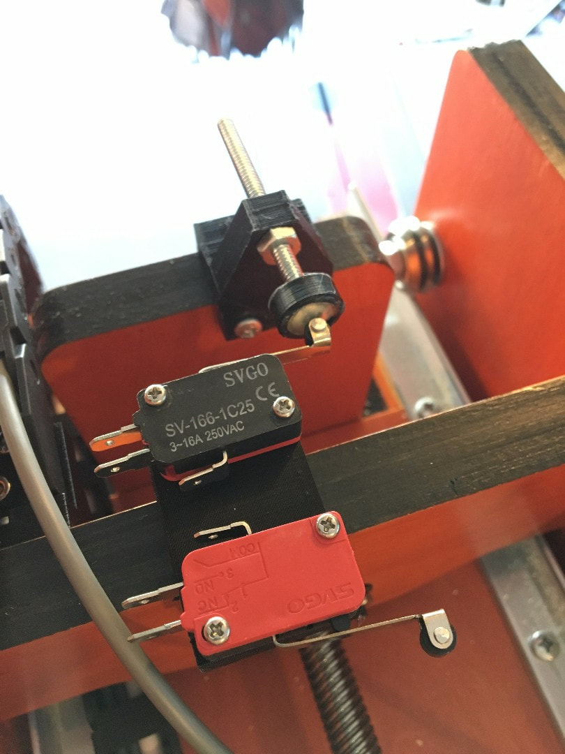
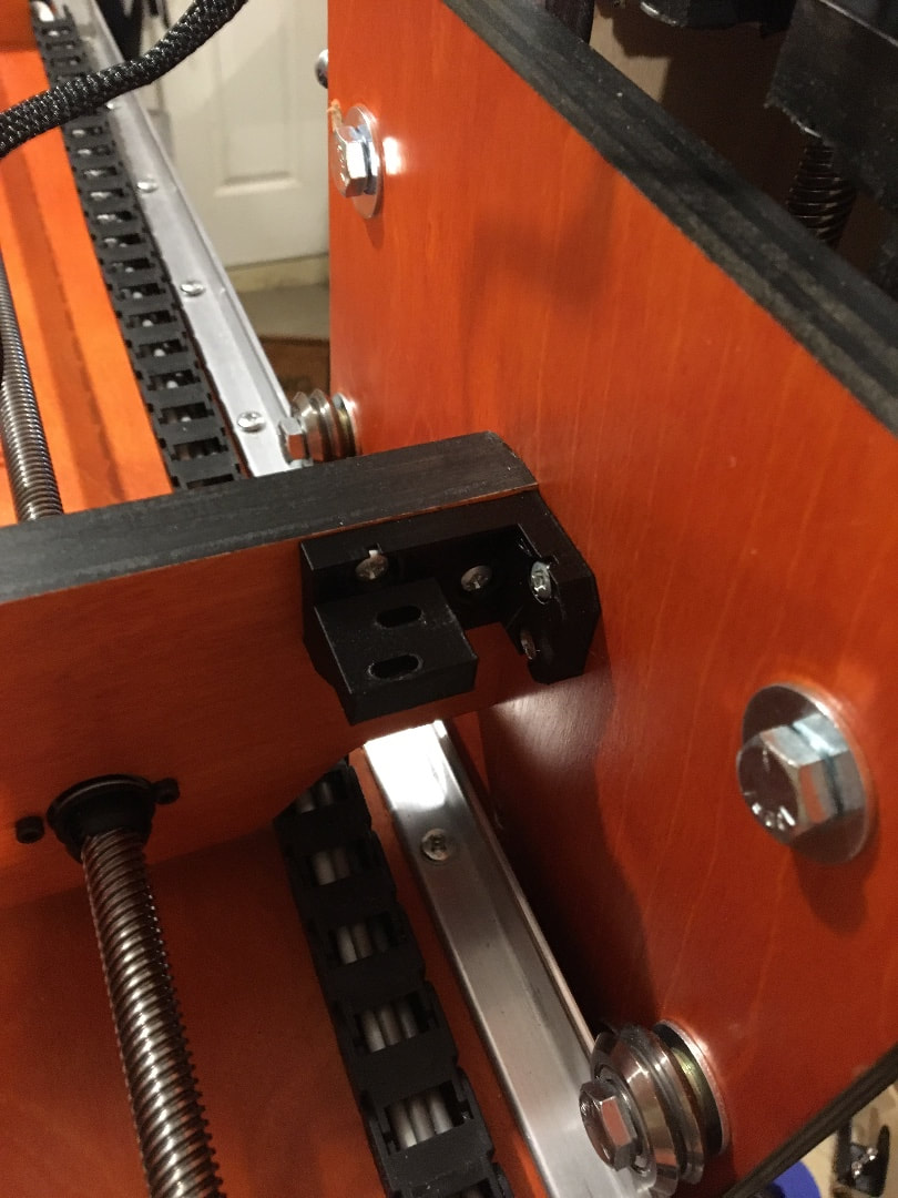
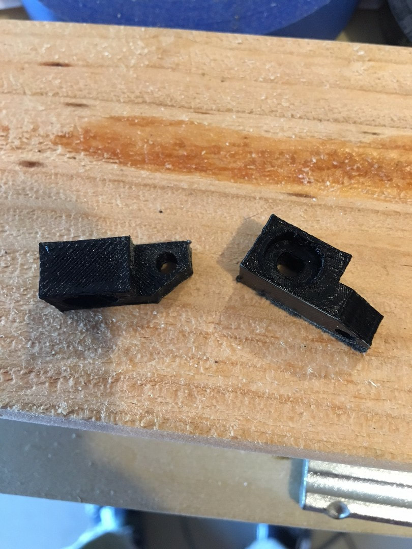
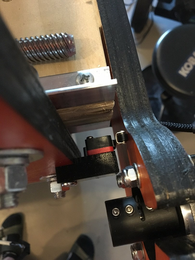
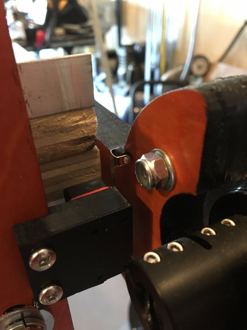
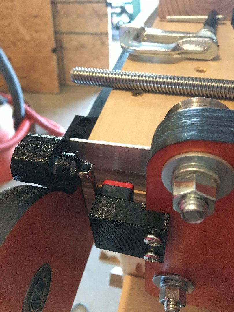
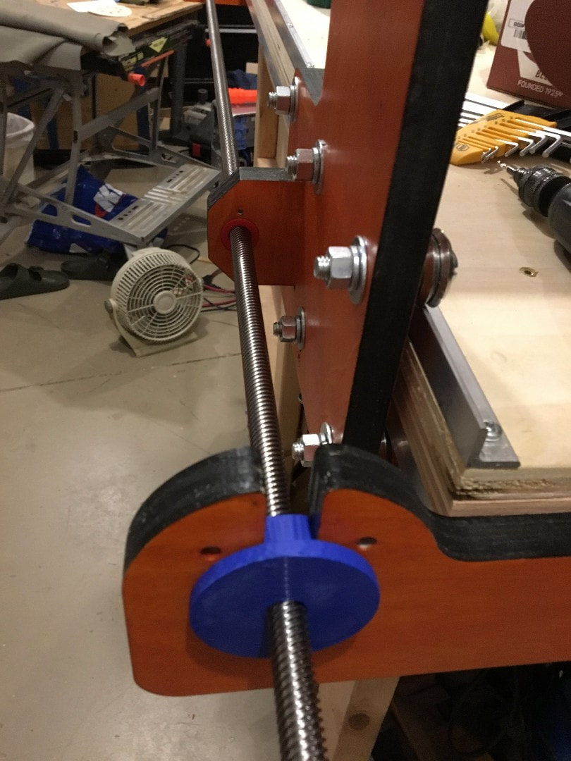
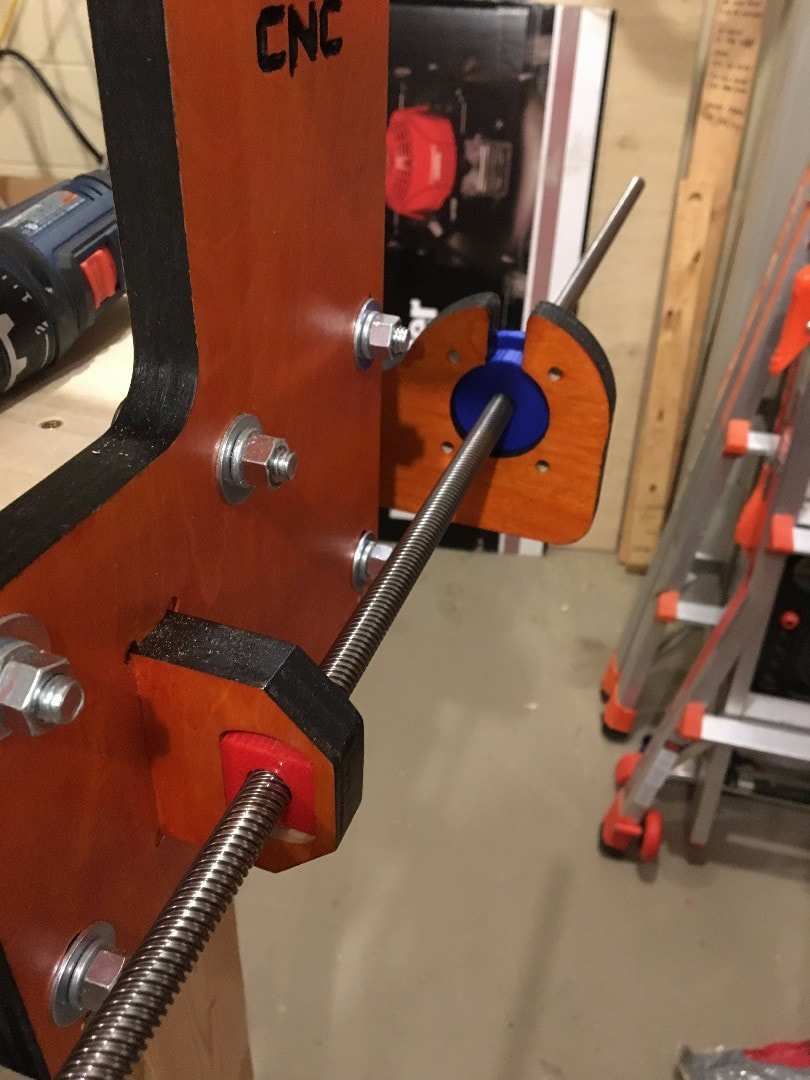
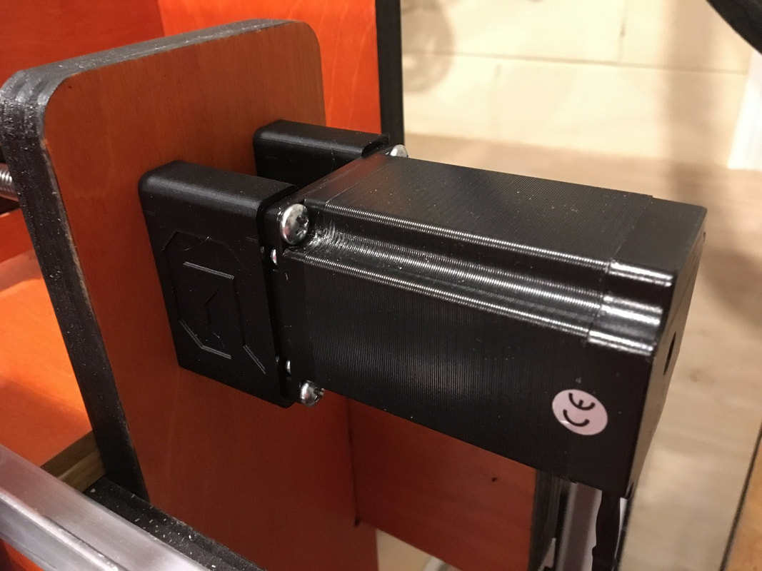
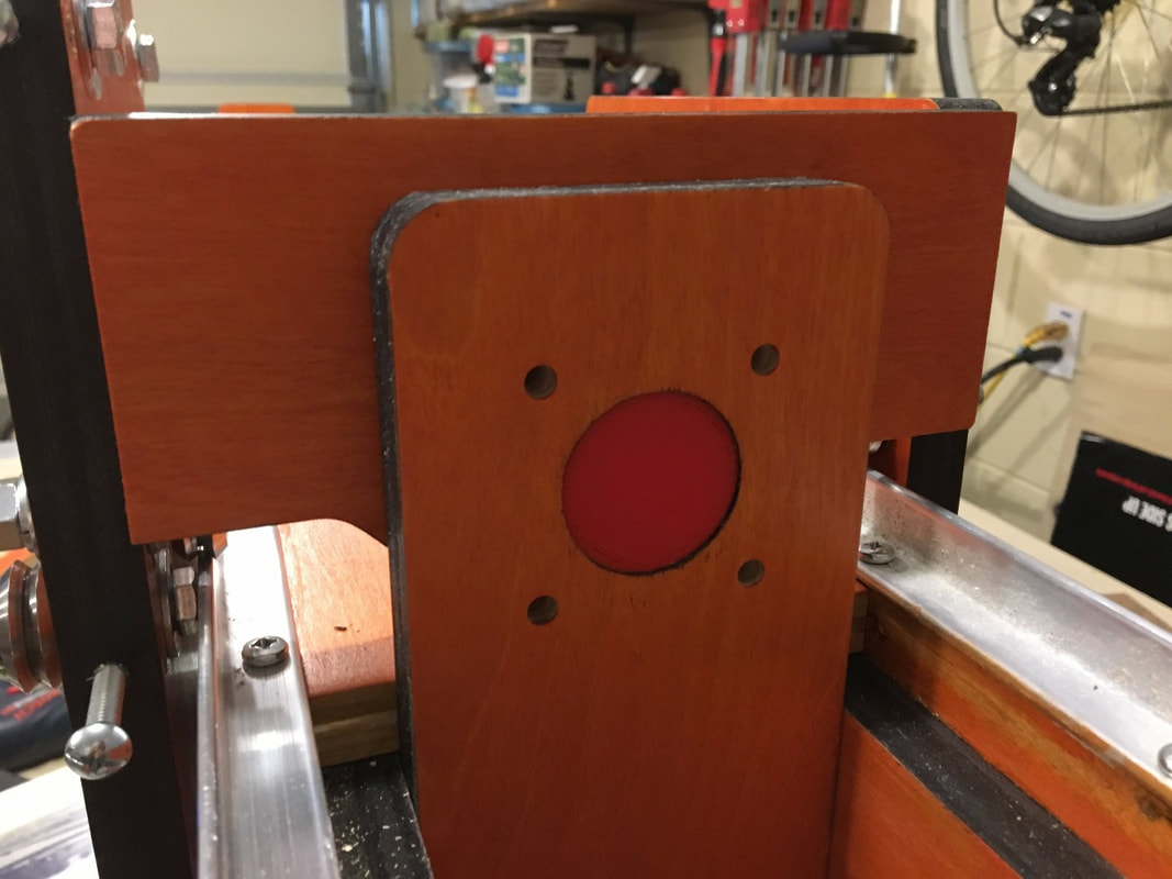
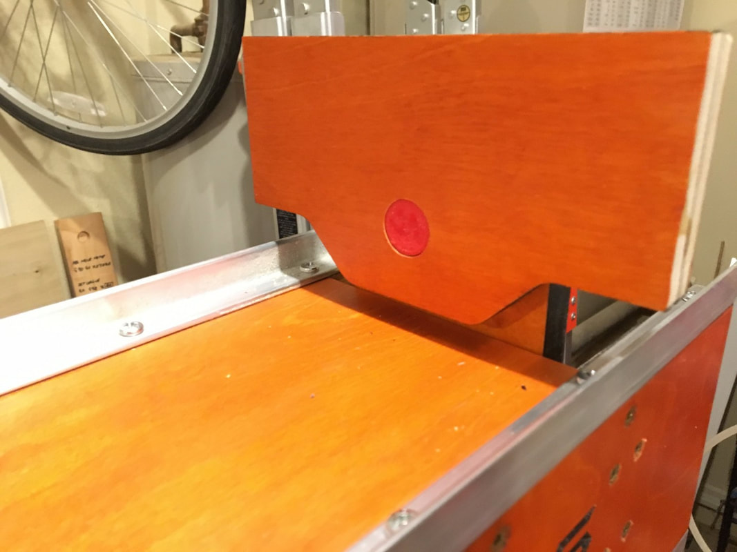
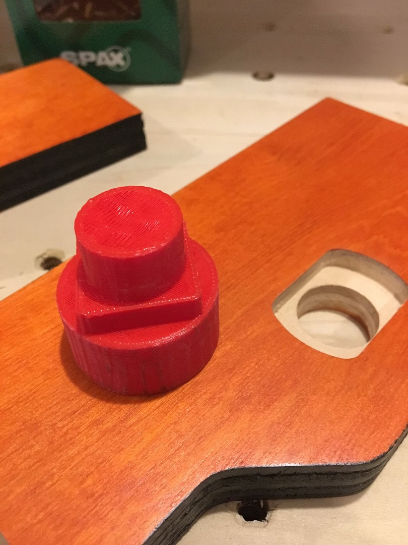
50 FEET 18/4 AWG - SHIELDED STRANDED WIRE / CABLE CNC / STEPPER MOTORS http://www.ebay.com/itm/50-FEET-18-4-AWG-SHIELDED-STRANDED-WIRE-CABLE-CNC-STEPPER-MOTORS/351744627477 And for the limit switches i used this wire, 22awg/4c Shielded Stranded Wire Cable - 50ft Grey http://www.ebay.com/itm/22awg-4c-Shielded-Stranded-Wire-Cable-50ft-Grey/152507246692?ssPageName=STRK%3AMEBIDX%3AIT&_trksid=p2060353.m2749.l2649 So i 3D printed the Y Axis limit switch pieces to mount them and also an adjustable bumper at the front of the Y. At the back i just let it touch the motor mount. The adjustable screw is a 10-24. Here is the link to the 3D printed files. https://www.thingiverse.com/thing:2515785 So i 3D printed a mount for the Panucatt Azteeg X5 GT CNC controller. The print files are located here. https://www.thingiverse.com/thing:2515771 There is a 1 piece and 2 piece which is easier to print depending on the filament used. Just waiting on a wire delivery to connect the limit switches. 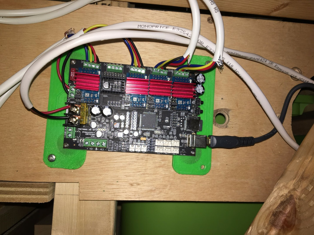 Ok so i started on the Y axis and decided another 3D printed jig to help align the front and back plates on the Y axis. Here are the 3D printed files. https://www.thingiverse.com/thing:2503731 I was able to get the front and back plates clamped on position and slide the machine back and forth to make sure it was running smoothly. So i managed to get the Y axis motors wired to separate Bigfoot stepper drivers and enslaved together to both move for the Y. Also made a simple program just to move through a few positions just to test out the software. i am using cncjs and so far i am very impressed with it. https://www.npmjs.com/package/cncjs I will post instructions on wiring the Azteeg X5 GT when i am done in case anyone else wants to use it. I have been impressed with it so far, easy connection with USB, on board limit/homing switch connections, solid state relay controls for my spindle and vacuum and the Bigfoot 3.0A stepper drivers are a great feature. The configuration is also a simple text file you just copy to the micro SD card which loads in a few seconds every time it boots. So the 3D printed Z axis alignment jigs worked a treat. When i installed the Z axis lead screw everything lined up and the lead screw went easily into the bearing on the bottom. 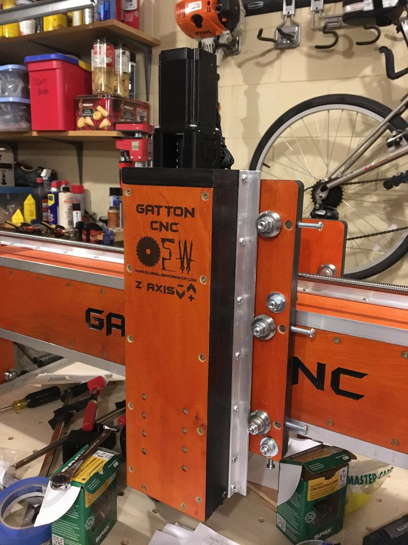 Managed to get the X axis lead screw and mounted. The motor and coupling is installed using the 3D printed Nema 23 motor spacer. I also received the Azteeg X5GT Smoothieboard i will be using as the CNC controller, with Bigfoot 3Amp motor drivers. So i 3D printed some alignment pieces for the Z Axis. I think it worked quite well as i realized i need a shim between the nut block and the front X plate. Hopefully now after full assembly everything should line up perfectly. Here are the files. https://www.thingiverse.com/thing:2479528 So i thought i would 3D print an alignment pin to assist with the positioning and trimming of the X axis hardware. https://www.thingiverse.com/thing:2469210 |
ArchivesCategories |
||||||


 RSS Feed
